- 您现在的位置:买卖IC网 > Sheet目录1905 > ATMEGA649V-8MI (Atmel)IC AVR MCU FLASH 64K 1.8V 64QFN
2010-2012 Microchip Technology Inc.
DS41440C-page 281
PIC16(L)F1825/1829
25.6.10
SLEEP OPERATION
While in Sleep mode, the I2C slave module can receive
addresses or data and when an address match or
complete byte transfer occurs, wake the processor
from Sleep (if the MSSPx interrupt is enabled).
25.6.11
EFFECTS OF A RESET
A Reset disables the MSSPx module and terminates
the current transfer.
25.6.12
MULTI-MASTER MODE
In Multi-Master mode, the interrupt generation on the
detection of the Start and Stop conditions allows the
determination of when the bus is free. The Stop (P) and
Start (S) bits are cleared from a Reset or when the
MSSPx module is disabled. Control of the I2C bus may
be taken when the P bit of the SSPxSTAT register is
set, or the bus is Idle, with both the S and P bits clear.
When the bus is busy, enabling the SSPx interrupt will
generate the interrupt when the Stop condition occurs.
In multi-master operation, the SDAx line must be
monitored for arbitration to see if the signal level is the
expected output level. This check is performed by
hardware with the result placed in the BCLxIF bit.
The states where arbitration can be lost are:
Address Transfer
Data Transfer
A Start Condition
A Repeated Start Condition
An Acknowledge Condition
25.6.13
MULTI -MASTER COMMUNICATION,
BUS COLLISION AND BUS
ARBITRATION
Multi-Master mode support is achieved by bus
arbitration. When the master outputs address/data bits
onto the SDAx pin, arbitration takes place when the
master outputs a ‘1’ on SDAx, by letting SDAx float high
and another master asserts a ‘0’. When the SCLx pin
floats high, data should be stable. If the expected data
on SDAx is a ‘1’ and the data sampled on the SDAx pin
is ‘0’, then a bus collision has taken place. The master
will set the Bus Collision Interrupt Flag, BCLxIF and
If a transmit was in progress when the bus collision
occurred, the transmission is halted, the BF flag is
cleared, the SDAx and SCLx lines are deasserted and
the SSPxBUF can be written to. When the user services
the bus collision Interrupt Service Routine and if the I2C
bus is free, the user can resume communication by
asserting a Start condition.
If a Start, Repeated Start, Stop or Acknowledge
condition was in progress when the bus collision
occurred, the condition is aborted, the SDAx and SCLx
lines are deasserted and the respective control bits in
the SSPxCON2 register are cleared. When the user
services the bus collision Interrupt Service Routine and
if the I2C bus is free, the user can resume communica-
tion by asserting a Start condition.
The master will continue to monitor the SDAx and SCLx
pins. If a Stop condition occurs, the SSPxIF bit will be set.
A write to the SSPxBUF will start the transmission of
data at the first data bit, regardless of where the
transmitter left off when the bus collision occurred.
In Multi-Master mode, the interrupt generation on the
detection of Start and Stop conditions allows the
determination of when the bus is free. Control of the I2C
bus can be taken when the P bit is set in the SSPxSTAT
register, or the bus is Idle and the S and P bits are
cleared.
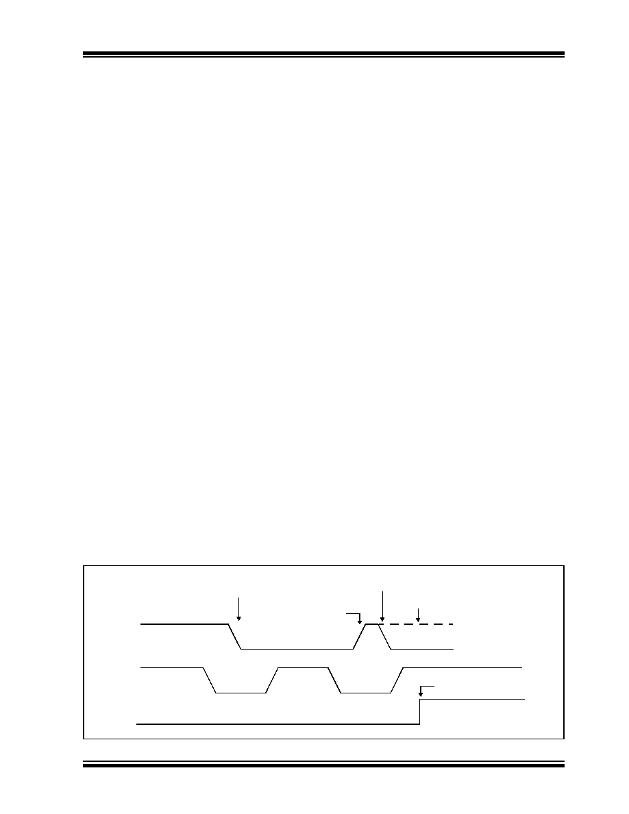
FIGURE 25-32:
BUS COLLISION TIMING FOR TRANSMIT AND ACKNOWLEDGE
SDAx
SCLx
BCLxIF
SDAx released
SDAx line pulled low
by another source
Sample SDAx. While SCLx is high,
data does not match what is driven
Bus collision has occurred.
Set bus collision
interrupt (BCLxIF)
by the master.
by master
Data changes
while SCLx = 0
发布紧急采购,3分钟左右您将得到回复。
相关PDF资料
ATMEGA8515L-8JUR
MCU AVR 8KB FLASH 8MHZ 44PLCC
ATMEGA8515L-8PJ
IC MCU AVR 8K 5V 8MHZ 40-DIP
ATMEGA8535-16JUR
MCU AVR 8K FLASH 16MHZ 44PLCC
ATMEGA8535L-8PJ
IC MCU AVR 8K 5V 8MHZ 40-DIP
ATMEGA88-15MT2
MCU AVR 8K FLASH 15MHZ 32-QFN
ATMEGA88-20AUR
MCU AVR 8K FLASH 20MHZ 32TQFP
ATMEGA88P-20AUR
MCU AVR 8KB FLASH 20MHZ 32TQFP
ATMEGA8HVA-4CKU
MCU AVR 8K FLASH 4MHZ 36-LGA
相关代理商/技术参数
ATmega649V-8MU
功能描述:8位微控制器 -MCU AVR 64K FLASH 2K EE 4K SRAM ADC LCD RoHS:否 制造商:Silicon Labs 核心:8051 处理器系列:C8051F39x 数据总线宽度:8 bit 最大时钟频率:50 MHz 程序存储器大小:16 KB 数据 RAM 大小:1 KB 片上 ADC:Yes 工作电源电压:1.8 V to 3.6 V 工作温度范围:- 40 C to + 105 C 封装 / 箱体:QFN-20 安装风格:SMD/SMT
ATMEGA649V-8MUR
功能描述:8位微控制器 -MCU AVR 64KB FLSH 2KB EE 4KB SRAM LCD8MHz1.8V RoHS:否 制造商:Silicon Labs 核心:8051 处理器系列:C8051F39x 数据总线宽度:8 bit 最大时钟频率:50 MHz 程序存储器大小:16 KB 数据 RAM 大小:1 KB 片上 ADC:Yes 工作电源电压:1.8 V to 3.6 V 工作温度范围:- 40 C to + 105 C 封装 / 箱体:QFN-20 安装风格:SMD/SMT
ATMEGA64A-AN
功能描述:8位微控制器 -MCU 16MHz 105C RoHS:否 制造商:Silicon Labs 核心:8051 处理器系列:C8051F39x 数据总线宽度:8 bit 最大时钟频率:50 MHz 程序存储器大小:16 KB 数据 RAM 大小:1 KB 片上 ADC:Yes 工作电源电压:1.8 V to 3.6 V 工作温度范围:- 40 C to + 105 C 封装 / 箱体:QFN-20 安装风格:SMD/SMT
ATMEGA64A-ANR
功能描述:8位微控制器 -MCU 16MHz 105C RoHS:否 制造商:Silicon Labs 核心:8051 处理器系列:C8051F39x 数据总线宽度:8 bit 最大时钟频率:50 MHz 程序存储器大小:16 KB 数据 RAM 大小:1 KB 片上 ADC:Yes 工作电源电压:1.8 V to 3.6 V 工作温度范围:- 40 C to + 105 C 封装 / 箱体:QFN-20 安装风格:SMD/SMT
ATMEGA64A-AU
功能描述:8位微控制器 -MCU 64K Flsh 2K EEPROM 4K SRAM 16MHz RoHS:否 制造商:Silicon Labs 核心:8051 处理器系列:C8051F39x 数据总线宽度:8 bit 最大时钟频率:50 MHz 程序存储器大小:16 KB 数据 RAM 大小:1 KB 片上 ADC:Yes 工作电源电压:1.8 V to 3.6 V 工作温度范围:- 40 C to + 105 C 封装 / 箱体:QFN-20 安装风格:SMD/SMT
ATMEGA64A-AUR
功能描述:8位微控制器 -MCU AVR 64KB FLSH 2KB EE 4KB SRAM-16MHz IND RoHS:否 制造商:Silicon Labs 核心:8051 处理器系列:C8051F39x 数据总线宽度:8 bit 最大时钟频率:50 MHz 程序存储器大小:16 KB 数据 RAM 大小:1 KB 片上 ADC:Yes 工作电源电压:1.8 V to 3.6 V 工作温度范围:- 40 C to + 105 C 封装 / 箱体:QFN-20 安装风格:SMD/SMT
ATMEGA64A-MN
功能描述:8位微控制器 -MCU 16MHz MLF 105C RoHS:否 制造商:Silicon Labs 核心:8051 处理器系列:C8051F39x 数据总线宽度:8 bit 最大时钟频率:50 MHz 程序存储器大小:16 KB 数据 RAM 大小:1 KB 片上 ADC:Yes 工作电源电压:1.8 V to 3.6 V 工作温度范围:- 40 C to + 105 C 封装 / 箱体:QFN-20 安装风格:SMD/SMT
ATMEGA64A-MNR
功能描述:8位微控制器 -MCU 16MHz MLF105C RoHS:否 制造商:Silicon Labs 核心:8051 处理器系列:C8051F39x 数据总线宽度:8 bit 最大时钟频率:50 MHz 程序存储器大小:16 KB 数据 RAM 大小:1 KB 片上 ADC:Yes 工作电源电压:1.8 V to 3.6 V 工作温度范围:- 40 C to + 105 C 封装 / 箱体:QFN-20 安装风格:SMD/SMT